2. Alignment (Find Origin and Calibration)
Scan coordinates are relative to the logical origin (outer frame edge, reference electrode center, focus). This page explains Find Origin, which determines the logical origin; Full Calibration, which measures the sensor tilt; and Z Focus, which only adjusts the focus. All operations are done in the [Alignment] tab of the stage panel.
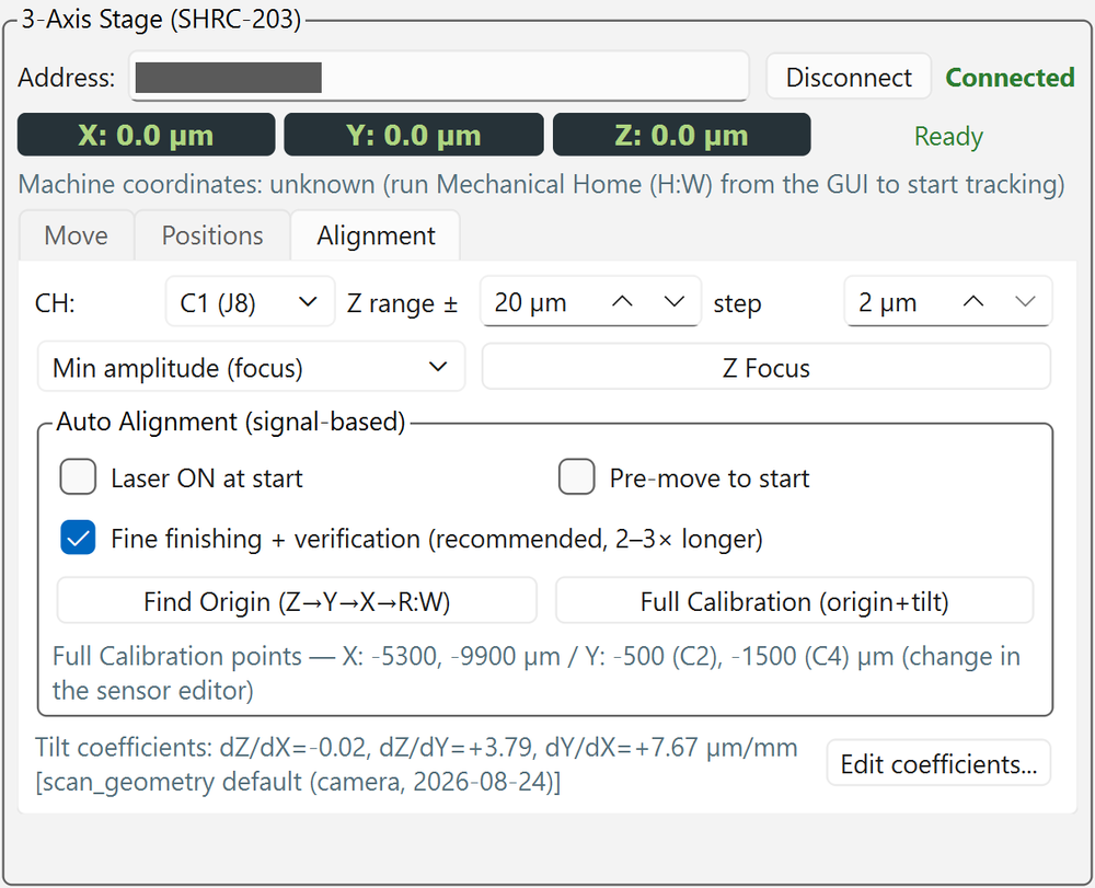
| Area | Contents | Details |
|---|---|---|
| Top rows (CH, Z range, step, method, [Z Focus]) | Adjust the focus only | Z Focus |
| "Auto Alignment (signal-based)" group | [Find Origin] and [Full Calibration] with their options | Find Origin, Full Calibration |
| Gray text below the group | Measurement points of Full Calibration (can be changed in the sensor editor) | Full Calibration |
| "Tilt coefficients" at the bottom | The currently active dZ/dX, dZ/dY, dY/dX and their source | Source of the coefficients |
The laser signal itself is the ruler
Find Origin does not use the camera; it uses the signal produced by the laser as the position sensor. On a metal electrode no light gets through and the signal drops to zero. The boundary is as sharp as the beam radius (a few µm), so the dip and edges of the amplitude profile give the position with µm precision. The amplitude is read with PAVA (waveform parameters).
Focus means "minimum amplitude"
The better the focus, the smaller the amplitude
The better the focus, the higher the local carrier density, which suppresses the LGAD gain and lowers the amplitude (plasma effect). Therefore the Z with the minimum amplitude is taken as the focus (confirmed by measurement on 2026-09-07; the old "maximum amplitude = focus" was wrong).
- Directly above an electrode the amplitude stays 0 even when defocused and no valley is visible, so always do the Z sweep on the silicon next to a strip.
- The gain-suppression valley is shallow (a few tens of %), so widen the range if no valley is found.
Before Find Origin
- The laser is ON and a signal is visible with the scope EXT trigger (it can also be turned ON automatically with [Laser ON at start])
- The beam is on the reference strip (C1), 50–200 µm inside the readout-side end of the exposed area (Coarse positioning; ±100 µm accuracy is enough)
- [Sensor] in the toolbar is correct
Find Origin
Press [Find Origin (Z→Y→X→R:W)].
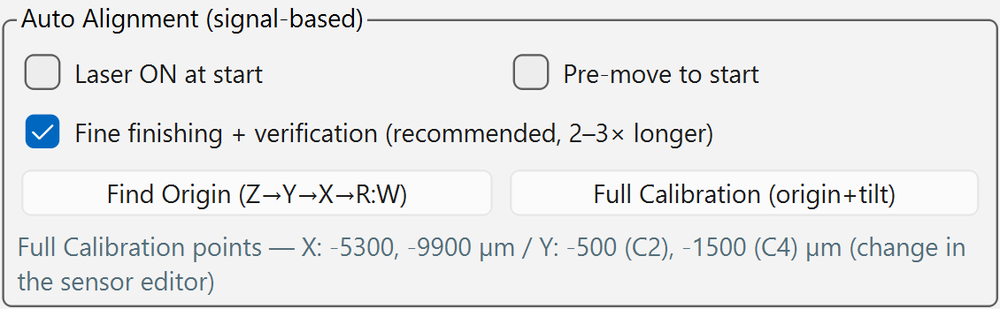
| Option | Default | Description |
|---|---|---|
| [Laser ON at start] | OFF | Turns the laser ON automatically if it is OFF |
| [Pre-move to start] | OFF | Turn ON when redoing it from an already-aligned state (logical origin = on the outer frame edge, no signal). Moves to the start position (on the reference strip, 100 µm inside the end) based on the current logical origin before starting |
| [Fine finishing + verification (recommended, 2–3× longer)] | ON | Fine sweeps in single-pulse steps with fits, and verification after R:W |
It takes about 2–3 min with coarse detection only, and about 7–12 min with fine finishing + verification ON. Progress is shown in the toolbar, and you can stop it with [Abort].
What it does
- Coarse Y sweep: detects the dip of the reference electrode and estimates the electrode center.
- Z sweep: on silicon 80 µm beside the electrode, finds the Z with minimum amplitude (= focus). If the valley is at the edge of the sweep, it re-centers automatically.
- Fine Y sweep: determines the electrode center Y with the beam in focus.
- X sweep: sweeps toward + (pad region side) and detects the edge where the signal disappears (boundary between the pad region and the exposed area). The X edge is detected 50 µm beside the electrode center.
- Z re-check: re-checks the focus on silicon.
- R:W: approaches the design offset +632 µm from the edge (= outer frame GND edge) from the negative side on all axes and performs Reset Logical Origin (R:W). The machine coordinates of the logical origin are saved automatically to the current sensor.
With fine finishing + verification (default ON), the following is done after steps 3–5.
- Each quantity is swept again in steps of one stage pulse (2 µm), reading each point 4 times (median), and determined to sub-µm with a model fit.
- Y electrode center: midpoint of the two edges, each fitted separately with erf (error function). Two sweeps are made and the difference is shown as reproducibility; one sweep in the reverse direction is made and the difference from the ascending sweeps is shown as the backlash estimate.
- X signal edge: same erf fit (2 sweeps + 1 reverse).
- Z focus: the valley is fitted with a Lorentzian + linear baseline, and the minimum of the curve is taken as the focus.
- Verification: after R:W, the electrode center Y, signal edge X and focus Z are measured again with the same fine sweeps. If any axis has a residual of one pulse or more, it is corrected and R:W is redone (up to 2 times).
Checking the result
The completion dialog shows the final residuals, backlash estimate and fit errors. Record them in the measurement log.
- Residuals below 1 µm are rounding left over from the 2 µm pulse grid and cannot be reduced further.
- Raw data of all sweeps are saved in
logs/alignment_<datetime>.csv.
Difference from an origin determined with the camera
The signal-based measurement itself is self-consistent to below 1 µm (analysis of the real-device log on 2026-10-05). The difference of a few µm from an origin set with the camera crosshair is thought to come from differences in how the reference is defined, such as the offset between the crosshair and the laser spot, the difference between the design value of 632 µm (pad end → outer frame end) and the actual size, and the approach direction (backlash).
Full Calibration
When you remount the sensor or change the jig, run [Full Calibration (origin+tilt)] instead of Find Origin. It takes about 8–12 min (coarse) or about 15–25 min (fine).
After Find Origin, for the standard sensor it measures the electrode center and focus Z at the following points.
| Measurement points | What is determined |
|---|---|
| X = −5.3 mm and −9.9 mm | Electrode center Y and focus Z → dY/dX (rotation), dZ/dX |
| C2 and C4 electrodes (Y = −500, −1500 µm) | Focus Z → dZ/dY, spacing of adjacent electrodes |
The resulting coefficients are saved to the current sensor profile, and the history is kept in logs/sensor_calibration_<sensor ID>_<datetime>.json.
The result dialog shows the measured spacing of adjacent electrodes and the residuals of the linear fit.
Do not trust the result blindly
Z is only determined in 2 µm steps and the valley is shallow. If the Z residuals exceed a few µm or the coefficients changed a lot since last time, re-run it or set the scan Z tracking to the "Measured Z" method (Auto scan).
The measurement points and offsets come from the current sensor profile. The measurement points of the current sensor are shown in gray text below the [Full Calibration] button. For non-standard sensors, check the measurement points in the sensor editor.
Find Origin and Full Calibration for pixel sensors
When you select a pixel-type profile with [Sensor] in the toolbar, the same [Find Origin] and [Full Calibration] buttons automatically switch to the pixel procedure.
- Start position: put the beam on the bonding pad of the reference CH, or within ±50 µm of the pad (unlike "50–200 µm inside the end" for strip sensors).
- Logical origin: the +X/+Y corner of the reference CH's pad. For the coordinate definition, see Pixel sensors.
| Strip type | Pixel type | |
|---|---|---|
| Ruler | Electrode (line with zero signal) and the end of the exposed area | Bonding pad (square with zero signal) |
| Find Origin | Y sweep → Z → fine Y → X edge → R:W | Y dip of the pad → Z (minimum amplitude) on silicon beside the pad → X dip of the pad → R:W at the pad corner |
| Fine finishing + verification | Yes | Yes |
| Full Calibration | Measures electrode center and Z at 2 X points and on neighboring electrodes | Same measurement on the pad centers of the other readout pixels, then plane fit (dZ/dX, dZ/dY), dY/dX along the row, and a pitch check |
Pixel Full Calibration has not been run on the real setup
As of 2026-11-01, Find Origin and Full Calibration for pixel sensors have been confirmed to agree within one pulse on a simulated sensor, but they have not yet been run on the real setup. Compare the results with previous values and with the camera view, and do not use them if they look wrong. The lever arm of the Full Calibration is only one pitch (about 500 µm), so the coefficients are only a rough guide. Note that the pixel analysis detects the pad positions automatically from the amplitude, so a small offset of the origin does not change the analysis results.
Source of the coefficients
The coefficients used for the tilt correction of scans are determined in the following order.
- Coefficients saved in the sensor profile (Full Calibration or [Edit coefficients...])
- For the standard sensor only, the defaults in
scan_geometry.py(camera measurement on 2026-08-24) - For any other uncalibrated sensor, 0 (no correction)
The currently active coefficients and their source are shown both at the bottom of the [Alignment] tab and in the "Tilt correction" group of the auto scan panel.
They are updated after every calibration, manual entry and sensor switch. The [scan_geometry default (camera, 2026-08-24)] in the screenshot above means that
the standard sensor has not yet been fully calibrated.
Entering coefficients manually
With [Edit coefficients...] you can enter dZ/dX, dZ/dY and dY/dX in µm/mm. The values are saved to the sensor profile,
and the history is kept in logs/sensor_calibration_*.json.
Z Focus (focus only)
Sweeps only Z at the current XY position and moves to the focus. Find Origin normally includes this, so it is mainly used to set the end points for the scan Measured Z method or to refocus manually.
- Laser ON; put the beam on the silicon next to a strip (where the signal is clearly visible; not directly above an electrode).
- Select [CH], [Z range ±] (default ±20 µm), [step] (default 2 µm = Z resolution) and the method (default "Min amplitude (focus)").
- Press [Z Focus]. It sweeps in one direction from below (against backlash) and moves automatically to the Z at the center of the valley. Takes about 20–30 s.
- If you start a scan right away, set Z tracking to "Coefficients (focus at current pos.)" to use this Z as the reference plane over the whole area (Z tracking).
While it runs, the scope is switched to sequence OFF and trigger NORM (they are set again when a scan starts, so you do not need to restore them).
- The sweep curve is saved in
logs/autofocus_<datetime>.csv. - If it reports that the valley cannot be identified, widen the range to ±30–50 µm or reposition the beam and run it again.
- On abort or error, it returns to the original Z.
Troubleshooting
| Message | Action |
|---|---|
| "No clear dip", "No clear edge" | Check that the beam is on the reference strip 50–200 µm inside the end, that the laser is ON, and that a signal is visible, then run again |
| "Valley too shallow" / valley cannot be identified | Widen the Z range to ±30–50 µm, or roughly focus with the camera first, then run again |
On abort or error, the stage returns to the start position if before R:W, or to the origin (0, 0, 0) if after R:W.