1. Startup and Device Connection
This page covers starting the GUI, connecting the devices, and getting the laser signal visible on the oscilloscope. Once this is done, go on to Alignment.
Prerequisites
The devices are powered on and LV 6.0 V and HV (−190 to −195 V at 33 °C) are applied (Measurement workflow).
1-1. Start the GUI
Start it in the GUI folder (Control PC and software).
Open a terminal on the control PC and run:
Use the English UI version (laser_gui_en) if you do not read Japanese.
1-2. Connect the devices
| Panel | Action | What to check |
|---|---|---|
| Oscilloscope | Check that the VISA field has the default (VICP::<scope IP>::INSTR; value in Internal information) and press [Connect] |
"Connected" is shown |
| 3-Axis Stage | Check that the address has the default (<stage IP>:<port>; value in Internal information) and press [Connect] |
"Connected" is shown and coordinates appear |
| Laser | Check that the port is COM5 and press [Connect] |
"Connected" is shown and the status display (Interlock, Trig, Freq, Tune, Head) appears |
| Focus Camera | [Start] | The image appears |
- After connecting, the button changes to [Disconnect].
- The laser panel input fields (trigger source, rep. rate, TUNE) are synchronized to the device's current values on connection.
- On connection, the stage speed (
stage_speed_pps) is set for all axes.
If you cannot connect, see Troubleshooting.
1-3. Mechanical Home (H:W)
The SHRC-203 needs a mechanical home right after startup.
- Make sure the sample (readout board) and the objective lens cannot collide. All axes move a lot.
- Press [Mechanical Home (H:W)] in the stage panel [Move] tab.
- When finished, machine coordinate tracking starts (Machine coordinates).
Run it from the GUI
You can also home with M-ORG on the JS-301 joystick, but machine coordinate tracking starts only when you run it from the GUI. Without tracking, "Machine coordinates: unknown" is shown and you cannot move to the saved origin.
1-4. Select the sensor
Select the DUT to measure with [Sensor] in the toolbar. Switching replaces the default scan range, tilt coefficients, saved positions and scope-channel-to-readout-pad mapping with those of the selected sensor.
- Normally use "Standard strip (500 µm pitch, 10 mm)".
- Register a new DUT from [Edit...] (Registering a new DUT).
1-5. Coarse positioning
Bring the beam roughly to the position where Find Origin starts. The target is on the reference strip (C1 for the standard sensor), 50–200 µm inside the readout-side end of the exposed area (about ±100 µm accuracy is enough).
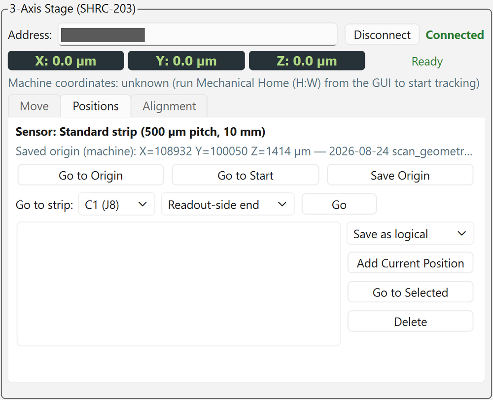
If an origin is saved (normal case)
Press [Go to Start] in the [Positions] tab. Based on the previously saved origin (machine coordinates), the stage moves onto the reference strip, 100 µm inside the readout-side end of the exposed area.
- [Go to Origin] moves to the previous logical origin (on the outer frame edge).
- Both use machine coordinates, so H:W in 1-3 must have been run from the GUI.
Right after remounting the sensor, or if no origin is saved
Using the camera crosshair as a guide, jog to the same position in the [Move] tab.
- Check [Crosshair] in the camera panel. If the image is too dark or too bright, adjust [Gain].
- Set the jog [Step] large (500 µm–1 mm) and move close to the readout-side end of the reference strip.
- Reduce the step (10–50 µm) and put the crosshair 50–200 µm inside the readout-side end of the exposed area.
- Roughly focus the camera image with the Z jog.
Jog direction
The arrows show the direction of motion in the camera image. The button text shows the actual axis and sign sent; ▲ is Y−.
Always keep the camera light OFF during measurement
The camera light is switched ON/OFF by hand inside the dark room. Turn it ON only while aligning with the camera, and always turn it OFF before Find Origin, TUNE optimization and measurement. The relation between TUNE and signal amplitude changes with the light ON/OFF.
Other functions of the [Positions] tab
| Function | Description |
|---|---|
| [Go to strip] | Select a CH and a place (Readout-side end / Middle / Far end); the coordinates are calculated from the sensor geometry and tilt coefficients and the stage moves there. The destination is on the electrode center line, where there is no signal, so before TUNE optimization or Z focus, shift Y by a few tens of µm to put the beam on silicon |
| [Go to pixel] (pixel sensors) | Select a CH and a place (Beside pad (signal) / Pad center (no signal) / 4-pixel corner) and the stage moves there |
| [Add Current Position] | Save the current position with a name. A position saved with [Save as logical] points to the same place on the sensor even after redoing Find Origin. A position saved with [Save as machine] is used for coarse positioning before the origin is found |
| [Go to Selected] / double-click | Move to a saved position |
| [Save Origin] | Save the machine coordinates of the current logical origin to the sensor (Find Origin does this automatically) |
1-6. Start laser emission
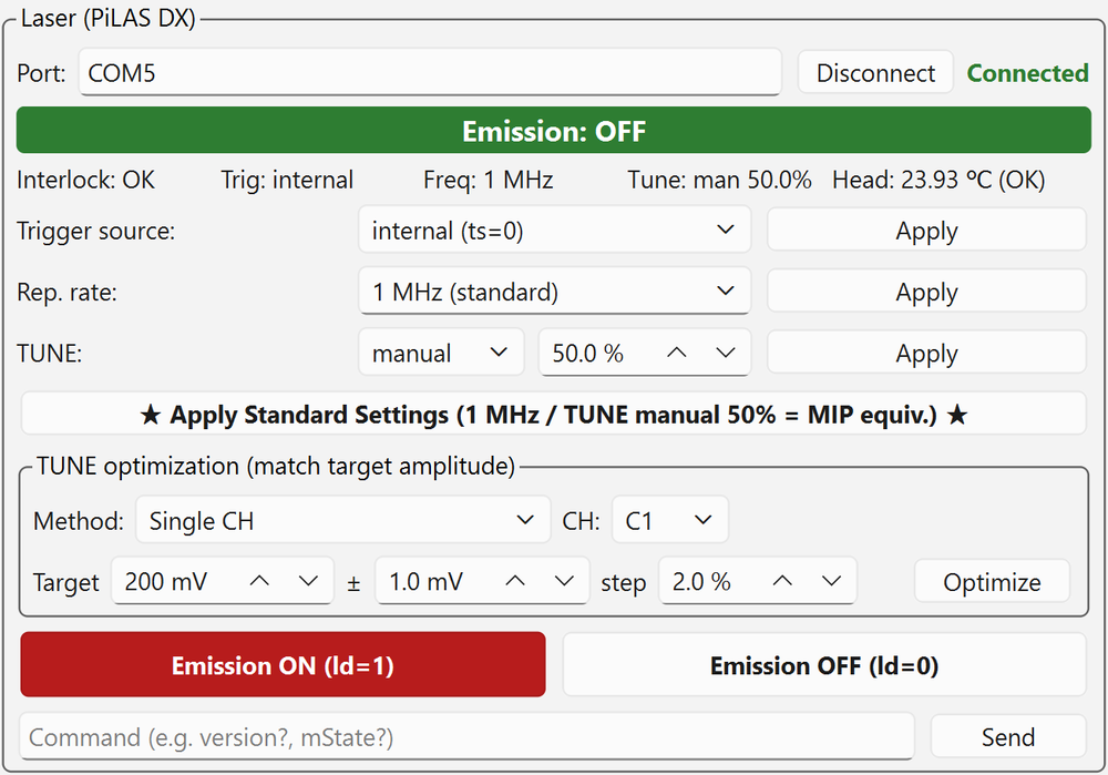
Press [★ Apply Standard Settings (1 MHz / TUNE manual 50% = MIP equiv.) ★] in the laser panel. The following standard conditions are sent in one go.
| Item | Standard |
|---|---|
| Trigger source | internal (ts=0) (the laser is the reference clock) |
| Rep. rate | 1 MHz |
| TUNE | manual, 50 % (already adjusted to MIP-equivalent at 1 MHz) |
After sending, check that the status line shows Trig: internal, Freq: 1 MHz and Tune: man 50.0%.
To use other conditions, change the Trigger source, Rep. rate and TUNE fields and press the corresponding [Apply] for each.
Do not set TUNE to auto
With TUNE on auto, the controller uses its calibration value for each rate, and the output is no longer MIP-equivalent.
Before firing the laser
Make sure the dark room (dark box) is closed and nobody is inside. The 1064 nm light is invisible (Safety).
Then press [Emission ON (ld=1)], check the interlock and optics in the confirmation dialog, and press [Yes]. The status display shows "Emission: ON" with a red band.
Difference from the conditions in the analysis note
The main scans in the analysis note (matome) were taken at 40 MHz, but the current standard is 1 MHz. The rate preset "1.25 MHz (TCT rec.)" is a general recommendation, not the standard for this setup.
Re-adjust TUNE after changing the rate
The optimal TUNE depends on the repetition rate. If you change the rate while keeping a manual TUNE tuned for another rate, the laser can drop below the lasing threshold and emit no light. TRIG OUT keeps coming in this case, so the scope waveform keeps updating but stays flat. Redo TUNE optimization after changing the rate.
1-7. Apply standard oscilloscope settings
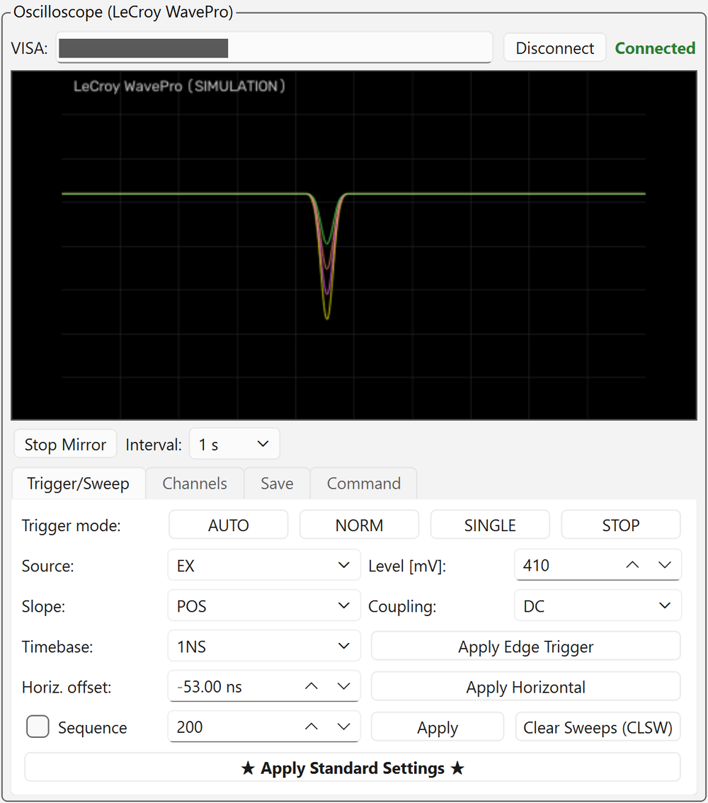
- Press [Start Mirror] in the oscilloscope panel to show the scope screen in the GUI.
- Press [★ Apply Standard Settings ★] in the [Trigger/Sweep] tab.
Standard settings:
| Item | Value |
|---|---|
| Trigger | EXT, DC, POS, 410 mV |
| Horizontal | 1 ns/div, horizontal offset −53 ns (display range +48 to +58 ns) |
| Vertical (C1–C4) | 50 mV/div, offset +100 mV (display range −300 to +100 mV) |
| Input coupling | DC 50 Ω (D50) |
| Averaging | OFF |
To change individual settings, use the [Trigger/Sweep] and [Channels] tabs.
Why the horizontal offset is −53 ns
The AC-LGAD signal arrives about 52 ns after the laser trigger (measured at 1 MHz). With the old setting of −4 ns the signal was visible because,
at 40 MHz (period 25 ns), the same signal seen from the trigger two periods later wrapped around to 52 − 50 = +2 ns.
With −53 ns the signal falls in the same window (+48 to +58 ns) regardless of the repetition rate.
This value is set by scope_trig_delay in config.py.
Keep averaging OFF
If it is ON, completion detection for sequence and SINGLE acquisition does not work and the scan times out.
1-8. Check the signal
On the scope mirror screen, check that a signal is visible on one of C1–C4.
- When the beam is on an electrode (metal), there is no signal. The destination of [Go to Start] is on the electrode of the reference strip, so there is almost no signal there. To check the signal, jog Y by a few tens of µm to put the beam on the silicon next to the strip (after checking, move back to the original position before starting Find Origin; an offset of about ±100 µm is acceptable).
- If no signal is visible, see Troubleshooting.
Once you see a signal, go on to 2. Alignment.